Project · Sumo Robot Version 1 and Version 2 · Chiang Mai
Miles’s sumo robot journey
I started with an Arduino Uno, an L298N driver and small TT motors. For Chiang Mai Robot Games 2026, I used what I learned to build a stronger Version 2 with a programmed Arduino, a Cytron motor driver, metal gearmotors and a custom yellow wedge chassis.
New build · August 2026
Version 2: built for CMRG 2026
Version 2 is not just a new shell. It is the result of testing the radio, learning the competition rules, choosing compatible parts, measuring everything for CAD, and changing the design when the evidence showed that the first hardware was not strong enough. Chiang Mai Robot Games runs from 28–30 August 2026, so this is our competition-weekend build update.
What I did on the way
- Reviewed the official rules: confirmed the 1 kg Junior class, 20 × 20 cm starting limit, wireless control and the requirement for a programmable control board.
- Proved the control idea: tested the HotRC transmitter and receiver, read steering and throttle pulses, and programmed tank-style mixing with a safe stop when the signal is lost.
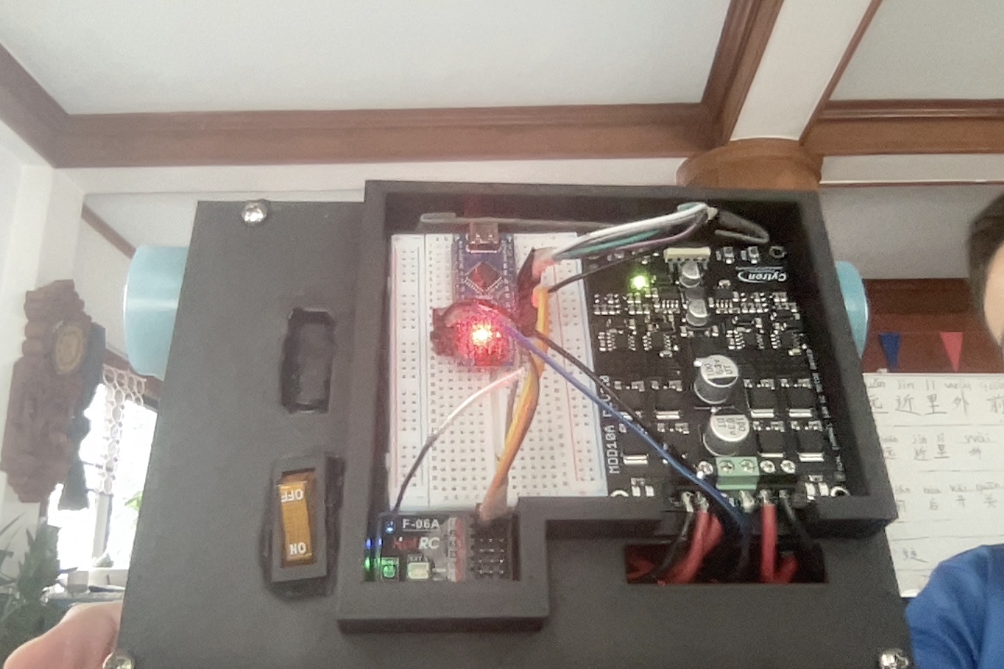
- Upgraded the drivetrain: moved from the learning setup’s L298N and TT motors to a Cytron MDD10A and two matched 12 V, 580 RPM GM25 metal gearmotors.
- Selected the power system: planned around a HeliCoxNano 2S 7.4 V, 1100 mAh, 30C LiPo and an LM2596 converter for regulated 5 V logic power.
- Designed before printing: measured component envelopes, checked the 200 × 200 mm layout in Tinkercad, left room for wires and terminals, and kept the battery low and removable.
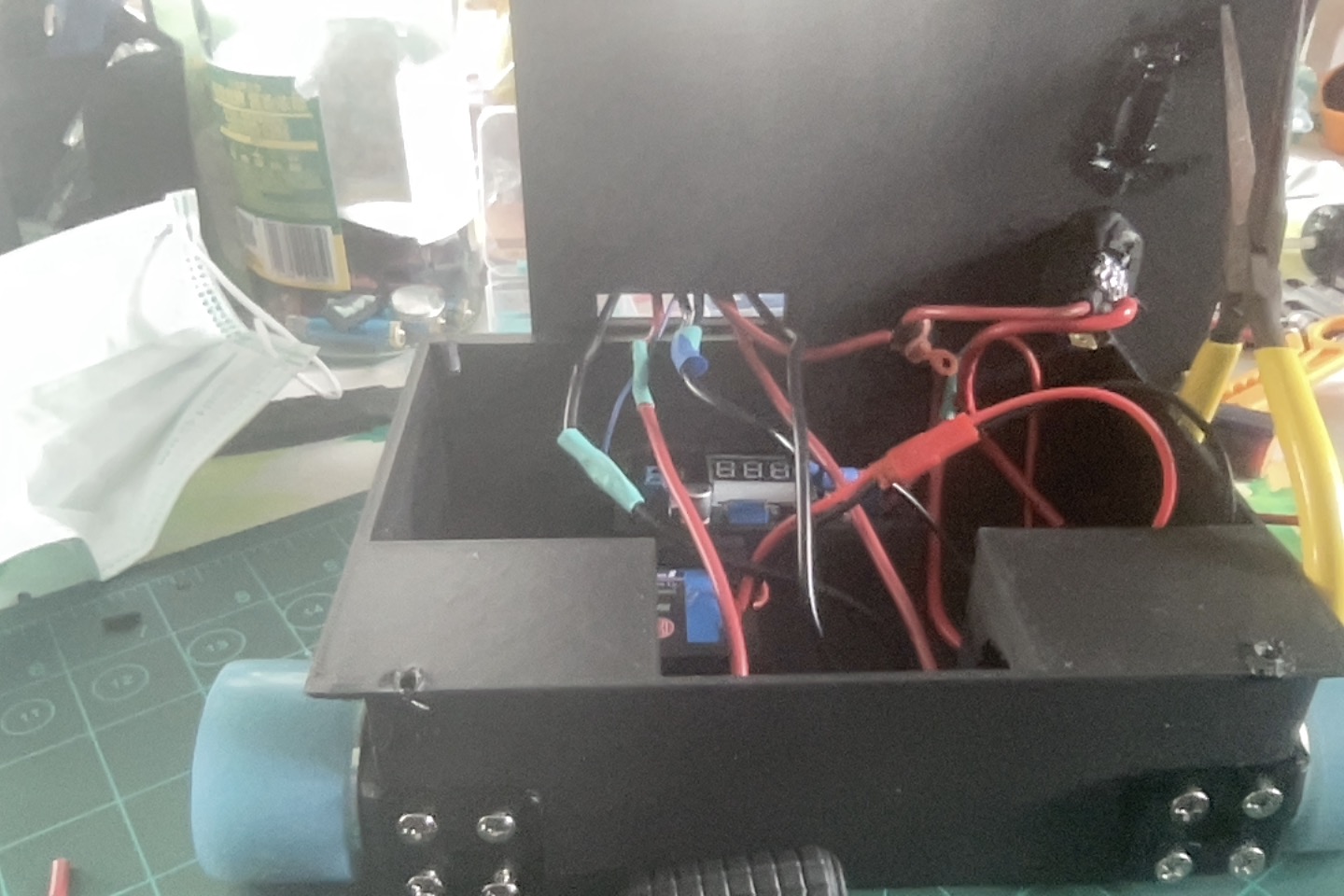
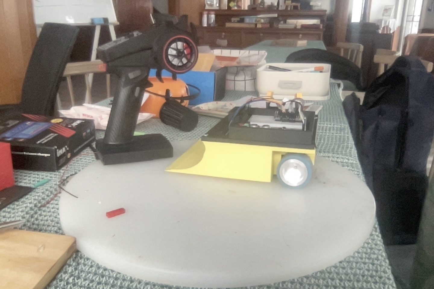
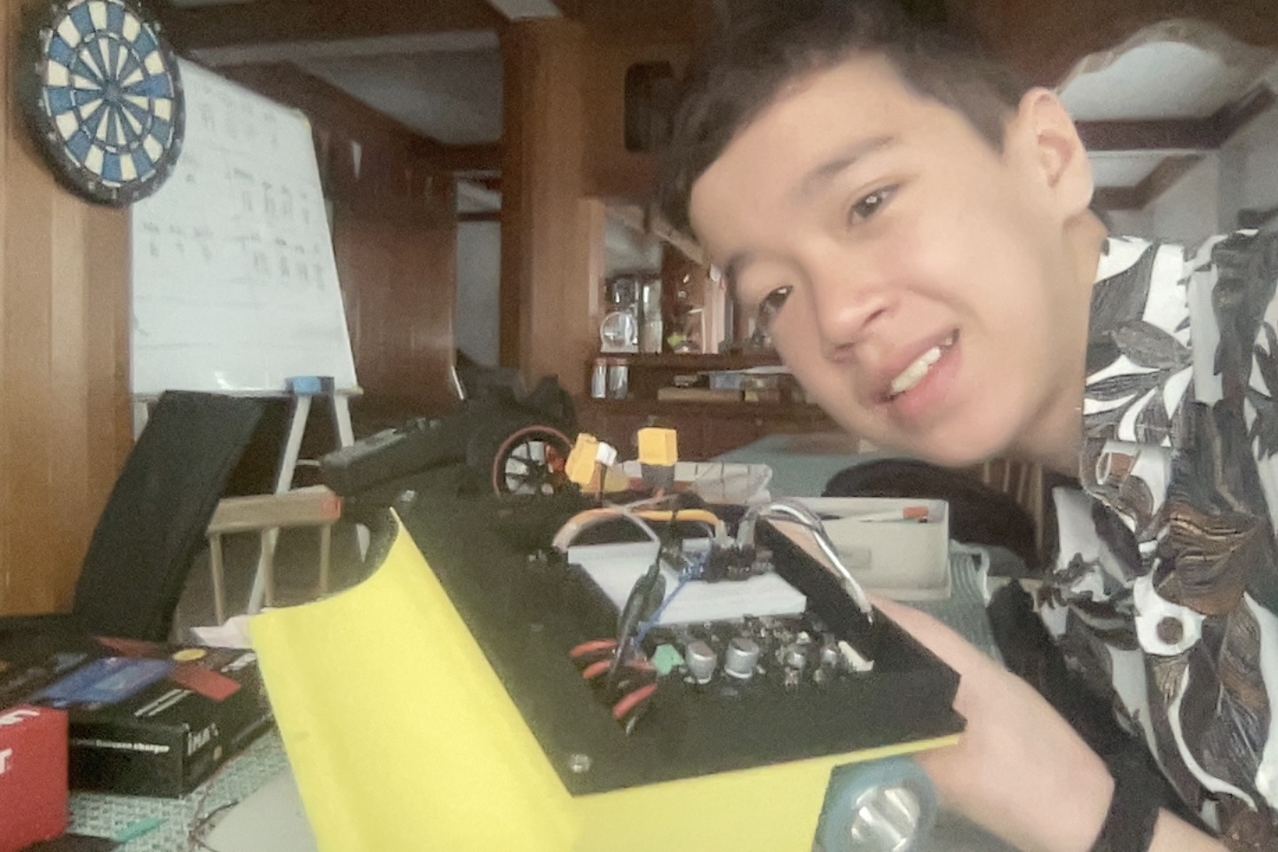
- Built the competition body: assembled a compact black chassis, installed the electronics and added a low yellow front wedge.
- Kept a real engineering record: saved test programs, wiring diagrams, parts decisions, safety notes and CAD reviews instead of hiding the mistakes and changes.
Final checks still matter
Assembly is a major milestone, but it does not automatically prove competition readiness. Before every match we still need to check weight and size, wheel clearance, secure wiring, radio failsafe behavior, battery condition, the main switch, and that nothing becomes hot.
The starting point
Version 1: what the first robot taught me
Motor hardware passed
An automatic six-step test drove the left motor forward/reverse, the right motor forward/reverse, and both motors together in both directions.
Radio signal passed
Both receiver channels produced stable servo pulses with no genuine zero-signal readings in a 1,100-line capture.
Integration still intermittent
When the radio program controls the complete drivetrain, the right side has been inconsistent. The latest work is isolating receiver mixing from loose connections and power sag.
Why document a robot that is not perfect yet? Because the failed paths and decisive tests are the useful part. This page separates what we proved from what we still suspect.
Build photos
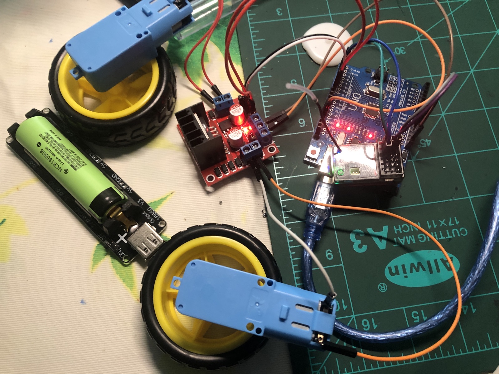
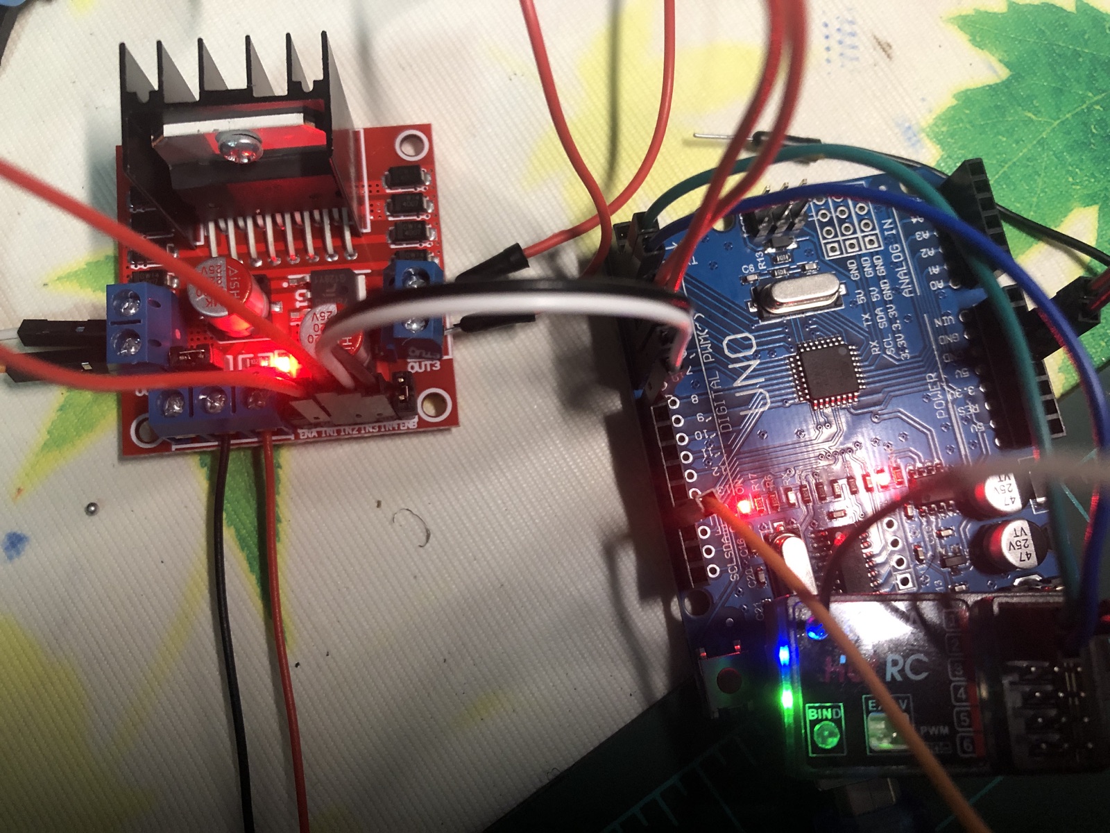
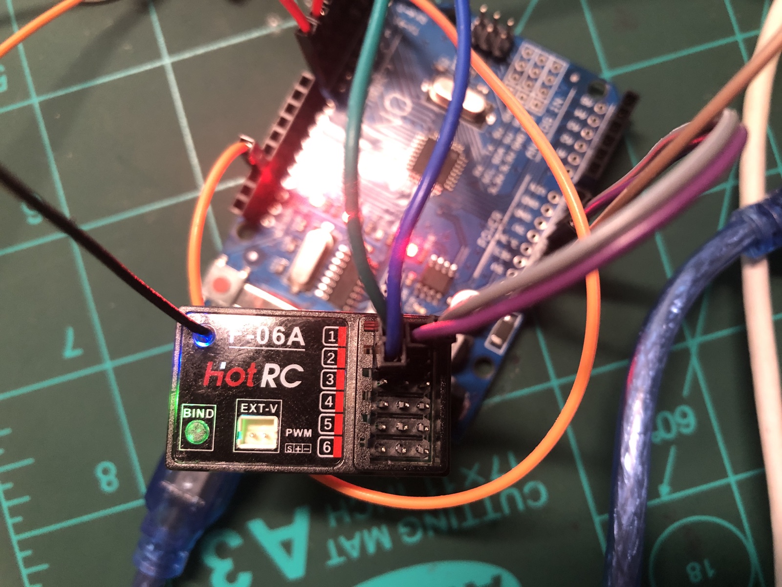
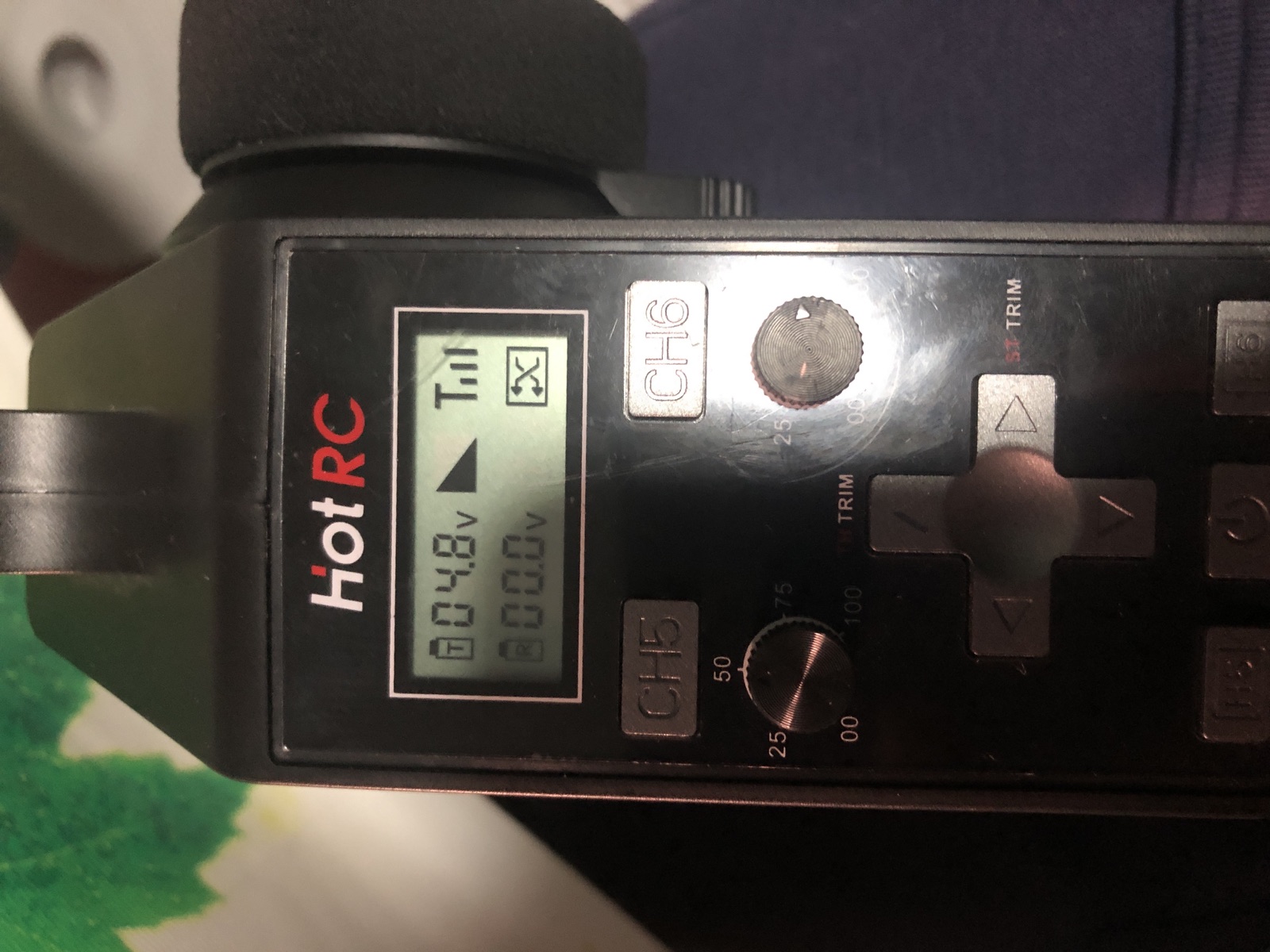
What we built
HotRC transmitter  ~~ radio ~~>  F-06A receiver
                                      │ CH1 + CH2 servo pulses
                                      ▼
                                  Arduino Uno
                                      │ D5–D8 direction signals
                                      ▼
4 × AA motor pack  ──────────────>  L298N driver  ─────>  2 × TT motors
       motor power                     ▲
                                       │ shared GND

Laptop USB (bench testing) ─────────> Arduino + receiver logic power
The Uno reads radio pulses and makes driving decisions. The L298N is the muscle: it switches the separate motor supply through two H-bridges. The Uno must never power the motors directly.
Confirmed specifications
| Part | Confirmed detail | Job |
|---|---|---|
| Controller | Arduino Uno-compatible board; CH340 USB serial at /dev/cu.usbserial-1110 | Reads radio and controls direction |
| Radio | HotRC F-06A six-channel PWM receiver and matching pistol-grip transmitter | CH1 steering; CH2 throttle |
| Motor driver | L298N dual H-bridge; ENA and ENB jumper caps installed | Drives two brushed motors |
| Motors | 2 × two-wire TT geared DC motors, rated approximately 3–6 V | Differential drive |
| Motor supply | 4 × matching AA cells in series (about 6 V fresh) | Feeds L298N motor input |
| Logic supply | USB during bench testing | Powers Uno and receiver |
| Radio calibration | CH1 ≈ 1230–1729 µs; CH2 ≈ 1030–1877 µs; neutral ≈ 1480/1450 µs | Defines dead zones and endpoints |
Verified wiring map
Disconnect the motor battery before moving any wire.
| From | To | Purpose |
|---|---|---|
F-06A CH1 signal (S) | Uno D2 | Steering pulse |
F-06A CH2 signal (S) | Uno D3 | Throttle pulse |
F-06A + | Uno 5V | Receiver power |
F-06A − | Uno GND | Receiver ground |
| Uno D5 | L298N IN1 | Left motor direction A |
| Uno D6 | L298N IN2 | Left motor direction B |
| Uno D7 | L298N IN3 | Right motor direction A |
| Uno D8 | L298N IN4 | Right motor direction B |
| Uno GND | L298N GND | Critical common reference |
| AA pack positive | L298N 12V/VIN | Motor supply positive |
| AA pack negative | L298N GND | Motor supply negative |
| L298N OUT1 + OUT2 | Left TT motor | Motor A |
| L298N OUT3 + OUT4 | Right TT motor | Motor B |
L298N header:  ENA | IN1 | IN2 | IN3 | IN4 | ENB
                     jumper  D5    D6    D7    D8   jumper
Motor wires belong on OUT1–OUT4, never on Arduino pins. Reversing the two wires of one motor safely reverses its physical direction. ENA and ENB remain jumpered for full speed.
Power lessons we learned
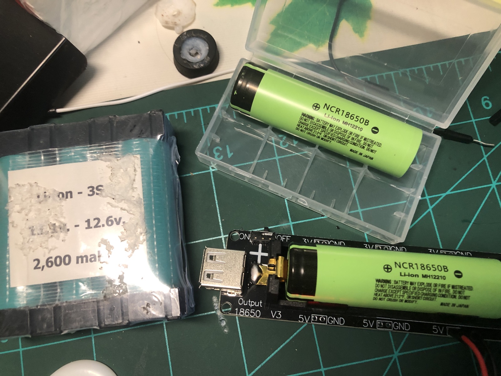
Do not use the 12.6 V pack here
We initially considered a three-cell 12.6 V pack. It exceeds the competition’s 12 V limit when fully charged and is a poor match for 3–6 V TT motors.
Use separate logic and motor paths
USB can power the Uno and receiver while four AAs power the L298N. Both supplies may be connected during testing, but Arduino GND and L298N GND must be joined.
- Arduino GPIO pins provide instructions, not motor current.
- The L298N loses voltage internally, so motor-terminal voltage is lower than battery voltage.
- LEDs can stay illuminated while weak cells collapse when both motors start.
- Solder and insulate motor leads; loose hook connections caused intermittent behavior.
Diagnostic timeline
- USB discovery: macOS detected the Uno clone as CH340 USB Serial at
/dev/cu.usbserial-1110. - Compilation: early errors came from pasting fragments inside
loop(). A complete sketch withsetup(),loop(), and motor helpers compiled successfully. - Receiver identification: the F-06A outputs servo-style PWM, not separate forward/back/left/right digital signals.
- Six-step motor test: IN1, IN2, IN3, IN4, both A directions, and both B directions all produced movement—six of six.
- Radio capture: more than 1,100 readings showed stable CH1 and CH2 pulses and revealed that the original 1400/1600 thresholds did not match the real endpoints.
- Control-model correction: a pistol-grip radio needs steering/throttle differential mixing, not one receiver channel assigned directly to each motor.
- Remaining symptom: receiver-driven tests became intermittent, particularly on the right motor, even though the automatic output test had proved that channel could operate.
Where we would value community help
The evidence points toward an intermittent connection, motor-supply sag, or a timing/ failsafe integration issue—not a completely dead motor or H-bridge. If you have built a similar Uno + F-06A + L298N robot, these are the most useful next checks:
- Measure AA-pack and L298N output voltage while both motors are commanded.
- Continuity-test D7→IN3, D8→IN4, ENB, OUT3 and OUT4 while gently moving each connector.
- Confirm whether sequential
pulseIn()reads are reliable enough for both simultaneous F-06A channels, or replace them with interrupt-based capture. - Recommend a more efficient dual brushed-motor driver for 3–6 V TT motors, if locally available.
- Suggest safe differential-mixing and failsafe values for CH1 1230–1729 µs and CH2 1030–1877 µs.
Please share advice with a reproducible test: what to disconnect, what to measure, the expected result, and what each possible result means. That style of help moved this build forward far more than swapping several things at once.
How these Version 1 priorities shaped Version 2
Better driver
The MDD10A replaced the inefficient L298N for the competition drivetrain.
Stronger mechanics
GM25 metal gearmotors, proper brackets, hubs and a custom chassis replaced the light learning hardware.
Planned power
The 2S LiPo, protection hardware and regulated logic supply were treated as one system.
Credits and links
- Builder: Miles Michelini — competition story
- Family and build support: Mike, Wendy and LaoYe
- Event: EasyKids Robotics Competition 2026, Chiang Mai · August 2, 2026
- Version 2 event: Chiang Mai Robot Games 2026 at Yupparaj Wittayalai School · August 28–30, 2026
- Purpose: Share the real process so another young builder can diagnose one variable at a time.